As oil and gas resources become harder to find, producers are forced to operate in
environments of ever increasing severity and risk. Often operating in High Temperature
High Pressure (HTHP) applications, the consequences of a catastrophic failure to
personnel, the environment and infrastructure are immense.
To help manage the increasing and unprecedented risk, the concepts of Safety
Instrumented Systems (SIS) and Safety Integrity Levels (SIL) were created and applied.
One such SIS type, is the High Integrity Pressure Protection System (HIPPS). A HIPPS is
an independently instrumented protective device, and acts as the last line of defence for
protecting downstream operations from over pressurization.
Typically certified to SIL3, a HIPPS gives operators the most dependable pressure
protection device available in the market today
PROTECTING YOUR ASSETS
Traditionally, the risk of over-pressure events has been managed through the use of
mechanical relief systems which open to relieve excess fluid to disposal systems such as
flare or holding tanks. Although simple, relatively low cost and widely available, mechanical
relief systems often require a large installation footprint, and are far from ideal when the
process fluid is flammable or toxic.
Typically operators select a HIPPS when:
New Installations
Existing Installations
HIPPS PRINCIPLE
Definition & Philosophy
HIPPS is the acronym for High Integrity Pressure Protection System. Main function of HIPPS is an independently instrum whose function is to protect an installation from the overpressure produced in the high pressure part of the same, isol pressure part from it.
Idea of HIPPS is to be used instead of traditional safety systems such as relief devices with four main advantages:
Environment protection: relief systems release the service fluid to the atmosphere which while HIPPS avoid flui released out of the system keeping the environment free of emissions.
HIPPS have to be a safety level equal or higher than the traditional relief methods; calculated safety levels show to be ten times more reliable than traditional methods.
Creating a frontier between two parts of the installation allows the downstream part of the valves of the HIPP lower pressure and therefore, to reduce the cost of pipes and related pressure equipments installed on that part.
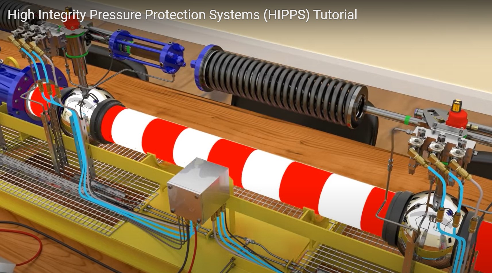
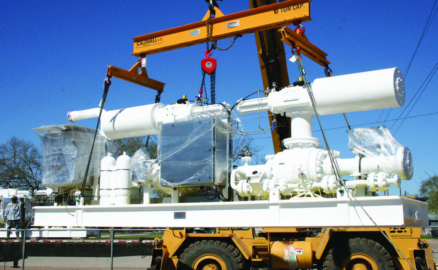
Hipps Scheme
The exact configuration of a HIPPS System will be dependent on the specific application;
however, as a minimum all HIPPS Systems include the following components:
One defining characteristic of all HIPPS is the duplication of system components to provide
failure redundancy; ultimately resulting in higher system integrity. Below is a common HIPPS
architecture showing redundant pressure transmitters, valve actuators, solenoid valves and
block valves.
APPLICABLE STANDARDS AND SAFETY INTEGRITY LEVEL
HIPPS are designed according to following standards:
Standards mentioned above are performance based so design of HIPPS is also based on the required Safety Integrit SIL has four categories, from 1 to 4, and it is defined by plant end user by means of making a risk analysis of the p related to the fulfillment of the tolerance risk: this means that SIL level results of the combination of two factors:
Safety Instrumented Function (SIF) defines the level of protection against failure and it is defined by the Probability o Demand (PFD). PFDavg is defined as the average probability of failure the safety function between 0 to 1. Standard defines the maximum allowable PFDavg value depending how often the demand of SIF is:
SIL Level is related to a this PFDavg value and must be considered for the complete functional loop, all its elements an between them
Maverick Valves – HIPPS IS PROVIDED
KEY FEATURES & BENEFITS
Maverick HIPPS Systems provides fully certified HIPPS with the following key features and benefits:
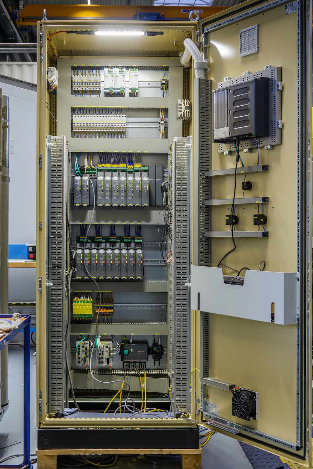
Working with our Sira/CASS certified technology partner, we provide TUV/AK6 certified logic solvers. Our logic solvers use standard, proven and function block software which allows for numerous options such as partial stroke testing, and valve function logging to support preventative maintenance programs. Communications to all major DCS systems and customized third party communications interfaces are also available. The SIS controller can be provided up to a range of IEC 61508 SIL3 platforms to include scalable 2oo3 pressure transmitters and 1oo2 solenoid valve packages. The final SIS choice is dictated by functionality and availability requirements, system costs and client preferences. All systems are independently third party certified to ensure compliance with all current legislation and industry standards.
Bespoke systems available for any HIPPS applications. Manifold designs to maximize robustness and reliability
Ball Valves
Typically will be trunnion mounted, double block bleed ball type due to proven tight shutoff, high reliability and low operating torque requirements. Ultimately the final valve
selection will be based on application specifications and end user preference.
Standard features
Optional features
Axial Valves
Design:
A stream lined body with constant sectional area, offers a very reduced coefficient resistance and gives larger Cv values for the same sizes.
Fluid is channeled into an annular path between the inner and outer bodies until it reaches the characterized cage. Smooth changes in flow direction and no turbulences contribute to lower noise levels. The high capacity, combined with the large range ability, make our axial valve to be acknowledged as the ideal design to control over the full range of process conditions with a single valve.
As an option extended body neck is offered for cryogenic operations, with a variety of sealing wafer. Zero emission is guaranteed by the O-ring seals combined with back- up packing. Distance between flanges is in accordance with ISA 75.03 when data are available or API 6D for larger sizes. All types of quarter turn actuator are easily mounted.
Advantages :
Actuators
Actuators assembled with MVM valves for the HIPPS systems can be pneumatic or hydraulic and they are supply in full compliance with customer specifications. Actuators include the control panel as specified, with solenoid valves.
Partial Stroke Test is available depend on SIL classification requirements.
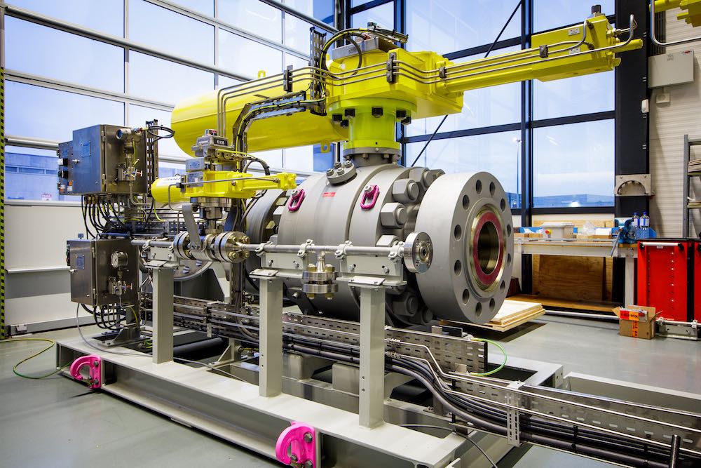
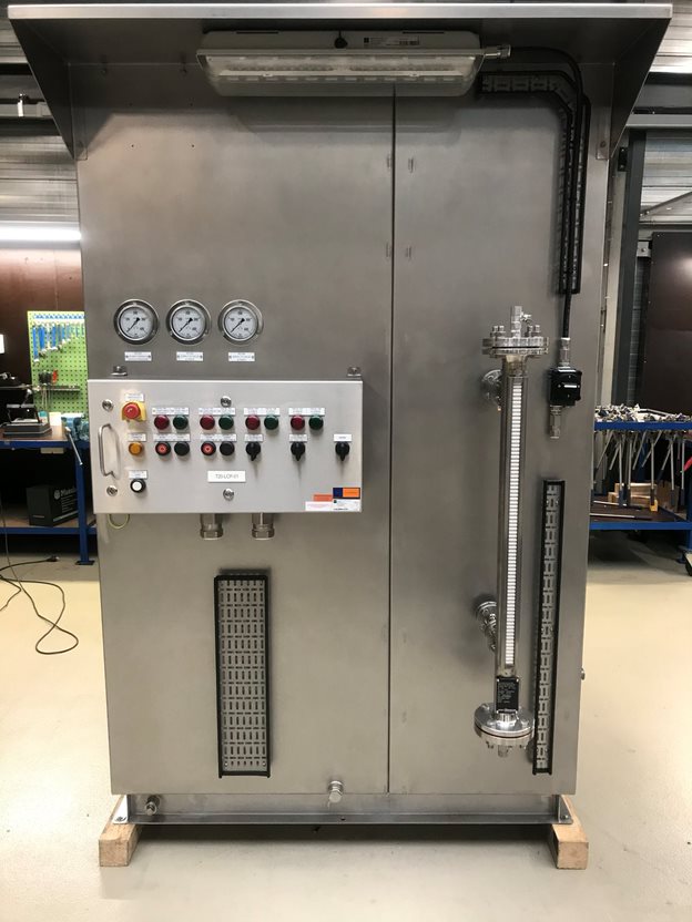
FACTORY ACCEPTANCE TEST / SIL CERTIFICATION OF THE COMPLETE HIPPS
Maverick has state of the art facilities for the assembly and testing of the final elements and integration of the HIPPS system.
MVM together with our partners offers full integration of the HIPPS elements in the factory: initiators, logic solver and final elements (valves + actuators + control panel):
Performance of Factory Acceptance Test of the completely integrated HIPPS. Test can be witnessed by customer or by his nominated Third Party Inspection agency.