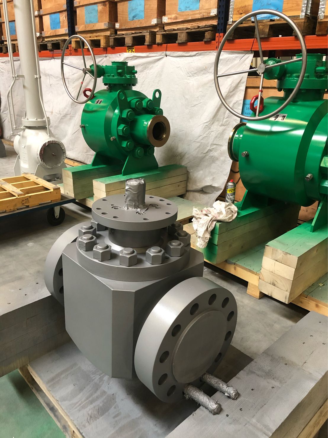
Special valve constructions to allow easy on-site maintenance and disassembly with quick access to ball and seats for inspection and repair.
GENERAL CONSTRUCTION
Top Entry valves are suitable for compression and re-injection systems, transmission pipelines, metering skids, Pig-launchers and receiving stations, Off- Shore and On-Shore platforms, gas storage and separations systems suitable for a wide range of high risk industry applications from severe abrasive and slurry to high temperature and cryogenic services, from subsea and LNG plants to topside installations. ERREESSE Top Entry valves can be welded directly onto the pipeline or to the manifold.
MATERIALS OF CONSTRUCTION
STANDARD FEATURES
| Construction | One piece bolted bonnet |
| Port | Reduced bore, full bore or fully piggable |
| Stem retention | Anti blow-out stem |
| Leakage rate | ISO 5208 rate A soft seated, rate B,C, D metal seated |
| Antistatic device | Included, the ball valve design includes an electric conductive connection between the internal parts of the ball valve and the body, providing the anti-static function. |
| Pressure relief | Automatic cavity relief to prevent overpressure in body cavity (self-relieving seats) |
| Sealing | Bi-directional, Double block & bleed (DBB) with sealing in both directions (DIB-1&2 upon request) Metal seated with Tungsten or Chrome Carbide coatings Primary metal secondary soft (PMSS) with differential hardness between the ball and seat to prevent galling of the substrate Soft seated with thermoplastic polymers (Nylon, PEEK, PCTFE), special polymers upon request Elastomers FKM, HNBR, EPDM O-Rings, special elastomers upon request |
| Drain | Drilled and threaded connections for all sizes |
| Vent | Drilled and threaded vent connections for sizes = DN150 (6″) < DN150 upon request |
| Stem grease injectors | Included for all sizes |
| Seat grease injectors | Included for sizes = DN150 (6″), < DN150 upon request |
| Lifting points | Included for sizes = DN150 (6″) or on valves of 250 kg min |
| Support feet | Included for sizes = DN150 (6″) or on valves of 250 kg min |
| Stem extension | Not foreseen for this model |
| Valve operation | Lever, Gear box or Actuator with position indicator and locking device |
| Material testing | Pressure containing & controlling parts to EN 10204 3.1 Materials in Sour Service according to NACE MR0175, MR0103, ISO 15156 Non-destructive testing (NDT) to API 6D, ASME B16.34 |
| Valve testing | Hydrostatic & pneumatic testing to API 6D, ASME B16.34, ISO 5208 (other upon request) |
TECHNICAL DATA
| Design | API 6D, API 6DSS, API 6A, ASME B16.34, ISO 14313, ISO 10423, ISO 17292 |
| Design pressure | ASME B16.34, EN 1092-1, ISO 17292 |
| Body wall thickness | ASME B16.34, ASME VIII Div. I, ISO 17292 |
| Face to Face | API 6D, ASME B16.10 Long pattern |
| Temperature range | -50° to 200°C (-58° to 392°F) |
| Pressures range | PN20 (ANSI 150) to PN420 (ANSI 2500) |
| Size range | DN15 (1/2″) to DN1400 (56″) |
| End connections | ASME B16.5 = DN600 (24″) Flanged RF,FF,RTJ MSS-SP-44 = DN550 (22″) Flanged RF,FF,RTJ ASME B16.47 A = DN650 (26″) Flanged RF,FF,RTJ ASME B16.25 Butt-Weld BW Clump (HUB) |
APPROVALS
| Safety Integrity Level | SIL 3 |
| Fire Safe | API 607, API 6FA, BS 6755, ISO 10497-5 |
| Area Classification | ATEX 94/9/EC |
| Pressure Equipment Directive | PED 97/23/EC |
| Fugitive Emission | ISO 15848/1 |
| Construction | API 6D, API 6DSS |