Valves suitable for Oil & Gas production, processing, transportation, distribution, chemical and petrochemical refining on above ground and below ground installations.
GENERAL CONSTRUCTION
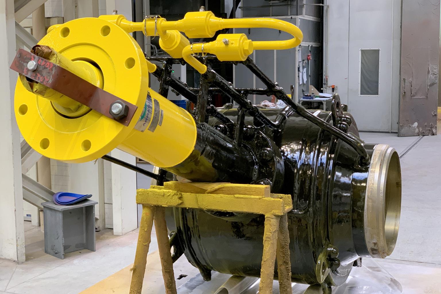
Trunnion ball valves have the obturator bounded by trunnions which do not allow axial displacements of the ball itself in the flow direction; line pressure compresses the seat onto the ball, the contact between surfaces generates the valve sealing; trunnion standard construction ensure automatic cavity relief in case of overpressure in body cavity; these valves can be selected for a wide range of applications with no specific limits to sizes and pressures. Fully welded constructions, both flanged or with welded ends, are a preferable solution when no maintenance is required on above ground or below ground (buried) installations and allows a real 0 leakage feature.
MATERIALS OF CONSTRUCTION
STANDARD FEATURES
| Construction | Fully welded body |
| Port | Reduced bore, full bore or fully piggable |
| Stem retention | Anti blow-out stem |
| Leakage rate | ISO 5208 rate A soft seated, rate D metal seated |
| Antistatic device | Included, the ball valve design includes an electric conductive connection between the internal parts of the ball valve and the body, providing the anti-static function. |
| Pressure relief | Automatic cavity relief to prevent overpressure in body cavity (self-relieving seats) |
| Sealing | Bi-directional, Double block & bleed (DBB) with sealing in both directions (DIB-1&2 upon request) Metal seated with Tungsten or Chrome Carbide coatings Primary metal secondary soft (PMSS) with differential hardness between the ball and seat to prevent galling of the substrate Soft seated with thermoplastic polymers (Nylon, PEEK, PCTFE), special polymers upon request Elastomers FKM, HNBR, EPDM O-Rings, special elastomers upon request. |
| Drain | Drilled and threaded connections for all sizes |
| Vent | Drilled and threaded vent connections for sizes = DN150 (6″) < DN150 upon request |
| Stem grease injectors | Included for all sizes |
| Seat grease injectors | Included for sizes = DN150 (6″), < DN150 upon request |
| Lifting points | Included for sizes = DN150 (6″) or on valves of 250 kg min |
| Support feet | Included for sizes = DN150 (6″) or on valves of 250 kg min |
| Stem extension | Not foreseen for this model |
| Valve operation | Lever, Gear box or Actuator with position indicator and locking device |
| Material testing | Pressure containing & controlling parts to EN 10204 3.1 Materials in Sour Service according to NACE MR0175, MR0103, ISO 15156 Non-destructive testing (NDT) to API 6D, ASME B16.34 |
| Valve testing | Hydrostatic & pneumatic testing to API 6D, ASME B16.34, ISO 5208 (other upon request) |
TECHNICAL DATA
| Design | API 6D, API 6DSS, API 6A, ASME B16.34, ISO 14313, ISO 10423, ISO 17292 |
| Design pressure | ASME B16.34, EN 1092-1, ISO 17292 |
| Body wall thickness | ASME B16.34, ASME VIII Div. I, ISO 17292 |
| Face to Face | API 6D, ASME B16.10 Long pattern |
| Temperature range | -50° to 200°C (-58° to 392°F) |
| Pressures range | PN20 (ANSI 150) to PN420 (ANSI 2500) |
| Size range | DN15 (1/2″) to DN1400 (56″) |
| End connections | ASME B16.5 = DN600 (24″) Flanged RF,FF,RTJ MSS-SP-44 = DN550 (22″) Flanged RF,FF,RTJ ASME B16.47 A = DN650 (26″) Flanged RF,FF,RTJ ASME B16.25 Butt-Weld BW Clump (HUB) |
APPROVALS
| Safety Integrity Level | SIL 3 |
| Fire Safe | API 607, API 6FA, BS 6755, ISO 10497-5 |
| Area Classification | ATEX 94/9/EC |
| Pressure Equipment Directive | PED 97/23/EC |
| Fugitive Emission | ISO 15848/1 |
| Construction | API 6D, API 6DSS |